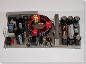
Sg3525 Ir2110 Smps Rare

Posted on  by  admin
Sg3525 Ir2110 Smps Rare 8,4/10 3226 reviews

To Search: SG3525 smps ir2110 Switch Mode Power Supply Circuit SG3525 IR2110 700 switching power pcb SG3525 smps ir2110 smps. Ferrite Transformer Turns Calculation for High- Frequency/SMPS Inverter.

Hi, I am building this smps (schematic attached ) I have a question, since it's a half bridge topology the other end of the transformer primary is attached to half the mains rectified (capacitor middle) via a capacitor, but heres the question, the transformer primary is attached via a capacitor to the middle point of the smoothing capacitors which makes now two capacitors in series to ground and to +ve, if im correct that makes the maximum voltage attainable at the primary not half but 1/4 that of the mains rectified correct? Can I just connect the float from the primary directly inbetween the smoothing capacitors without the additional capacitor? My devices are IRFP 460 they handle up to 400v if i remember correctly. Can I just connect the float from the primary directly inbetween the smoothing capacitors without the additional capacitorNo. The series capacitor 1uF/480V is necessary to make sure the current through the primary is balanced and averages zero.

If you connected the primary directly to the float terminal, the cap would need to move to the other side of the primary. The capacitor also limits the energy transferred on each cycle of the conversion. It prevents high DC currents in the transformer primary. The directly rectified mains that is divided up with that capacitor divider can be thought of as a fairly high impedance source at DC but a very very low impedance source at the switching frequency. A fairly clever way of doing it I guess when there is no transformer to use the center tap for this float node. In a perfect world I think the series capacitor in question could be eliminated but I would not do it.

Slight differences in tolerances could cause an imbalance in that capacitor divider. The series capacitor will not cause any loss. It is only responsible for passing AC and at the switching frequency it will not even appear to be there. Also I wanted to ask one more question, see in the attached schematic there is a feedback optoregulator ' 4n25' now it has two zener diodes in series connected to it, I assume the zener voltage is choosen to be such that its about 4 volts below the maximum output of the rectified high frequency AC coming from the transformer? Also can I use more than two zener diodes in series but each being a different zener voltage? I just need to get some particular voltage but I dont have the correct zeners at hand but I have other ones I could combine hem in series to get the needed one? Firstly, the capacitor.

You should stick with a 1uF bipolar capacitor. Reducing the voltage spec might cause a problem when switching the unit on or off.

There is a reason why they specified those values. It needs to be a good low loss cap, not electrolytic. The ripple current is quite high. Secondly, the chain of zenners. You can make the chain from what you have but check them before you turn it on. The 4 volts is needed to allow for the opto-coupler LED voltage, plus takes into account the difference between zenner knee voltage and at what voltage the zenner will be conducting enough current to turn on the LED in the opto-coupler.

Sg3525 Ir2110 Smps Rare

For example if I need 80 volts I put 76 volts on the zener series connection and the feedback changes either the duty cycle or frequency? And the output voltage hence changes correct?Yes. But it is not precise, it is simple design, maybe +/-1V.

301 refers to the recording studio, but it can also be read '3 as 1' or '3 minus 1.' Esbjorn Svensson Trio: Leucocyte; Interviews. Esbjorn Svensson: Requiem. Esbjorn svensson trio 301 rarest. Esbjorn Svensson Trio 301 Rarest. IMBD-099.rar.rar 2.61 GB. Esbjorn Svensson Trio - 301 Esbjorn Svensson Trio - 301: Everything And Nothing CD1. In January 2007 e.s.t. Were on tour in Asia and Australia performing shows in Tokyo, Osaka, Yokohama, Jakarta, Perth and Sydney. It was their third tour of Japan and. Find great deals on eBay for esbjorn svensson trio. Shop with confidence.

All small triangles are connected together as a common reference. They are all connected to the negative of the rectified AC.

The small transformer and 7812 regulator provides a 12V DC supply on the neg rectified AC input. It is needed to start and run the converter. You must be careful testing that circuit. I use a 1:1 mains isolation transformer and earth the common reference when working inside live switching power supplies. Notice that the transformers and opto-isolator form an island of floating supply, often with 350V DC and capable of killing.

See attached. Well my question was about whether i can connect together the ground from the mains bridge rectifier and also the ground from the small rectifier that i have after the small transformer which feeds the IC's? The small transformer is made with a rectifier a smoothing capacitor and a zener which gives me about 24 volts DC that I feed into the sg3525 and ir2110, the maximum allowed for the sg is 35 volts and for the ir2110 25volts. But should i connect the ground from the low voltage bridge rectifier together with the one coming from the mains rectifier? I ask this because they are both separate units as we know and can't there arise some ground currents or unbalances etc?

Is it possible to also keep the separately connected the mains for the driver transistors and the small ground for the IC's or isn't that possible because the IR2110 driving the mosfet needs both the +ve and ground as a reference to drive the gate properly or what? Well my question was about whether i can connect together the ground from the mains bridge rectifier and also the ground from the small rectifier that i have after the small transformer which feeds the IC's?All triangles inside the red box MUST be connected together. You must stop calling those triangles ground.

Those triangles are all a common reference rail at the negative rectified AC voltage. They must not be connected to anything else as they are referenced to Earth for RF noise only through the 2.2nF/250V capacitor. For DC and power they are referenced to the rectified mains AC through the 'float' circuit. You should not be working on what is called 'live chassis' mains circuits without more experience. You are really beginning to worry me. Live chassis circuits have only one aim in their life, which is to take your life. It will try to kill you when you least expect it.

I know everyone here on PF always insists on some overly worried safety advice, but don't worry Baluncore, I have been working with electronics for some years now, just because I'm not a pro at SMPS and some other stuff doesn't mena I don't know were the mains voltage is and were it's not.I actually always take great caution when doing things around mains simply because as a kid I got zapped by mains many times and it was out of curiousity back then I had a passion for those things back then but didin't had the respect towards them that I have now in my early twenties. Also I want to say thanks for your help.as I said I asked this about the grounds beacuse I the situation confused me a little because the mains has just a rectifier but the low voltage IC supply has a transformer feeding them so they are basically sort of only magnetically coupled to the mains versus the rest of the circuit high voltage side is directly coupled to the mains via the bridge. But still I assume the load current from the transistors will all flow towards the mains rectifier negative not the small rectifier because there the current would have no where to flow since it's not directly coupled to mains correct? In other words connecting them together posesses no danger to the IC's? Oh and also when I power it up I guess it would be better to always have some kind of a load attached to the outputs from the secondary side.? Now I want to share something, i put the whole thing together and it worked. Worked in the past tense is correct.i attached a 70w 230 volt bulb to the outoput and it worked the bulb was glowing and i got that nice feeling inside.because the mains has just a rectifier but the low voltage IC supply has a transformer feeding them so they are basically sort of only magnetically coupled to the mains versus the rest of the circuit high voltage side is directly coupled to the mains via the bridge.Ok, this is why you are getting safety warnings.

Just because the IC is fed power through the low voltage transformer does not mean that it is isolated from the line voltage. The actual + and - 70 volt output is isolated but that is where it ends. Did you not look at the diagrams baluncore posted with the red line drawn around?

You now know what happens to SMPSs when they are being tested. What can I say? You attribute failure of the prototype to bad luck. The truth is that you do not understand the importance of knowing the circuit and getting everything right before applying power. For example, how did you calculate the area of the heat-sink needed on the MOSFETS?

Sg3525 Inverter Schematic

Did you check the temperature of the components with an IR thermometer before increasing the load? Did you use polycarbonate, ceramic or electrolytic capacitors in appropriate places? Did you earth the common output or did that voltage float far enough from earth to break down the PCB insulation? But still I assume the load current from the transistors will all flow towards the mains rectifier negative not the small rectifier because there the current would have no where to flow since it's not directly coupled to mains correct? In other words connecting them together posesses no danger to the IC's?Have you looked at the “Modified smps 2.png” I attached to post #15.

The 7812 regulated supply is a quite independent and isolated 12V supply that is only needed to power the SMPS chips on the –170V rail of the rectified AC. It is needed to power the SMPS chips before the switching supply can start. Ok, I am getting a fair amount of criticism some fair and some unfair.Heres what I have done. I really take care about mains and line voltages, after all I am soldering my stuff with a home made iron that I wound myself and it is being supplied about 40 volts from a transformer so it's decoupled from mains, by the way I did this because commercial budget and cheap soldering irons after a fair amount of use and time tend to zap you so I got this done, used the very old case of the mains powered soldering iron just rewound the coil and put some new isolation in.

As for the smps, the heatsink is actually better than needed, I used an old CPU heatsink from a dell computer drilled some holes in it and attached the transistors.Its a copper sink and i had a thermometer attached all the time when I was working with it it never got over 30 celsius, but even without looking i felt it with my hand and it was room temp so heat isnt an issue here. (yes the transistors are isolated from the sink just in case you ask) after all Baluncore if you were reading what I wrote I had no way of checking the temp after the increase in load because while attaching the 500w bulb, obviously i turned the power off, and then turned it on again as would seem logical. The blast was so fast noone could have checked any temps.

Yes I used standard polyester little boxes were a unipolar cap was asked and electrolytics were a sign was noted also ofcourse electrolytics for the mains rectifier smoothing. Yes I looked at your diagram.I also agree that in terms of space and weight an SMPS beats an oridnary transformer and ofcourse it's because of the switching frequency.although we could still debate whether they are a universal ' one size fits all' solution to everything. Well i guess will have to sort out the problem with some thinking reading trial and error alltogether.I mainly think it has to do with the transformer as it is (core material windings etc) not matching the transistors under certain conditions, like heavy load, I mean after all the schematic is not that hard it's either back EMF that killed the setup or shoot through. Or the load was simply too big for the IRFP460 although i doubt that since they are rated Idc 18 amps at max 400 volts. But who knows.

Sg3525 inverter schematic

Sadly i dont have a 200w bulb should have started with gradual increase in load. Please can you comment anything about the condition why the devices failed after all the things I have said about how the setup is built?

Can a shoot through happen in this situation shouldn't the IR2110 have some built in circuit that senses such a condition in pin5 and alters the firing rate of the mosfets, the lower one at that point, or am I expecting too much from a simple single half bridge driver IC? I have attached a circuit I found online, it seems someone has put a small circuit that senses shootthrough and shutdowns the oscillator IC, or maybe im understanding it wrong.

Coments are closed